Aug 06, 2026
Content
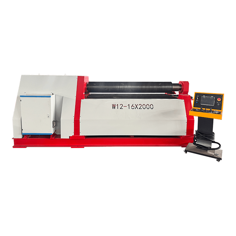
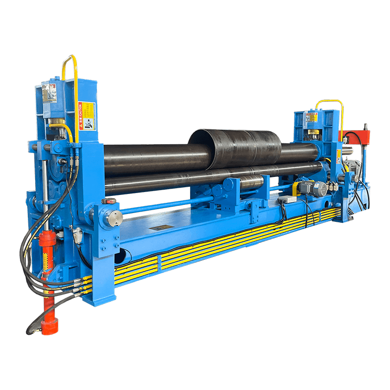
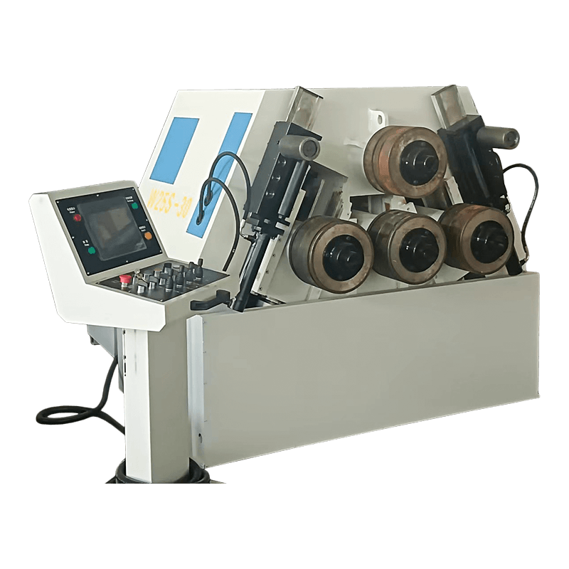
A hydraulic plate rolling machine forms flat metal sheet into a curved or cylindrical shape by feeding the plate between rotating rolls while hydraulic cylinders apply steady, adjustable pressure to bend the material a small amount with every pass. The top roll (or the side rolls, depending on the design) is pushed down or inward by hydraulic power rather than by gears or screws, so the operator can fine tune bending force in real time and hold that pressure consistently across the full length of the plate.
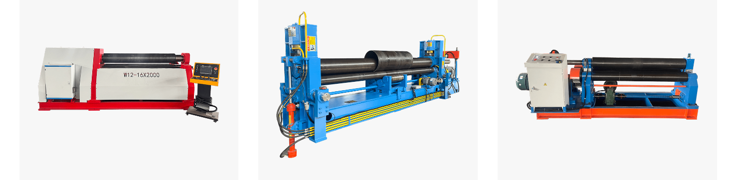
This is the working principle behind almost every machine marketed today as a Steel Plate Rolling Machine, Hydraulic Plate Bending Machine, or 4 Roll Plate Rolling Machine, whether it sits in a small metal fabrication shop or runs as a Heavy Duty Plate Rolling Machine on a shipyard production line. The sections below break the process down step by step, compare the common roll configurations, and explain how material type, plate thickness, and roll arrangement affect the final result.
| Feature | 3 Roll Plate Rolling Machine | 4 Roll Plate Rolling Machine |
|---|---|---|
| Pre-bending step | Often needs a separate pass or fixture | Built into the rolling cycle |
| Plate flipping required | Sometimes, on asymmetric designs | Rarely needed |
| Typical use case | General workshop fabrication | Precision and repeat production runs |
Every plate rolling machine, no matter how many rolls it uses, relies on the same underlying idea: three or more contact points push the plate out of a straight line, forcing the metal past its yield point in a controlled way so it takes on a permanent curve instead of springing back flat. On a hydraulic machine, the force behind that pressure comes from oil driven cylinders rather than a mechanical screw, which is why hydraulic designs are generally easier to fine tune mid-cycle.
Picture the plate resting on two lower support rolls while a top roll presses down between them. As the plate is driven forward and backward, the top roll gradually descends in small increments, tightening the curvature on each pass. The hydraulic cylinder holding the top roll keeps the downward force steady even as the plate resistance changes near the edges, which is one reason hydraulic systems tend to produce a more even curve across the plate width than a purely mechanical setup.
Adding a fourth roll, or shifting the side rolls horizontally instead of only moving the top roll vertically, changes how the plate edges are handled. This is the main technical difference between the roll configurations covered in the next sections, and it directly affects how much flat, unrolled material is left at the plate ends after forming.
A typical CNC hydraulic plate rolling machine is built from a fairly small set of parts working together. Understanding what each part does makes it much easier to read a machine specification sheet or troubleshoot a rolling problem on the shop floor.
Simplified structural layout of a 4 roll hydraulic plate rolling machine, shown in isometric style for clarity
Once a plate is loaded, a hydraulic plate rolling machine moves through a fairly consistent sequence regardless of whether it is a compact workshop unit or a large heavy duty plate rolling machine handling structural steel.
On a manual machine, the operator judges each pass by eye and by measuring the gap; on a CNC hydraulic plate rolling machine, the roll positions and pressure targets are programmed in advance, so repeat parts come out with less variation from piece to piece.
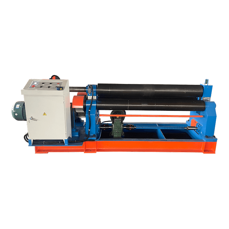
Most buyers researching a Hydraulic Plate Rolling Machine end up comparing three roll and four roll layouts, since both are widely available and each suits a different production pattern.
| Configuration | How It Bends the Plate | Best Suited For |
|---|---|---|
| 2 Roll | Plate is pre-bent on a press, then wrapped around a driven roll | Thin gauge sheet, light fabrication |
| 3 Roll, Asymmetric | Top roll moves down between two fixed lower rolls | General workshop and repair work |
| 3 Roll, Double Pinch | Both lower rolls move to pinch and pre-bend the plate | Medium volume steel fabrication |
| 4 Roll | Top and bottom rolls align vertically, side rolls move horizontally | Precision cylinders, repeat production, heavy duty plate rolling machine tasks |
Illustrative pre-bending convenience score by roll configuration, scale of 1 to 10, higher means less separate pre-bending work required
A Steel Plate Rolling Machine is not limited to a single metal type. The main variable that changes from one material to the next is how much resistance the plate offers as it bends, which in turn affects how many passes are needed and how much hydraulic force the machine must sustain.
Illustrative relative forming resistance by material type, based on typical roll bending behavior, not a fixed measurement
Thicker plate needs a larger roll diameter and more passes to reach the same curvature as thinner material, because the outer fiber of a thick plate has to stretch further to follow the bend. This is why a machine rated for a certain plate rolling machine capacity lists both a maximum thickness and a matching minimum roll diameter, and why pushing a plate near the upper thickness limit usually means slowing the feed rate and taking lighter, more frequent passes.
Typical relationship between carbon steel plate thickness and rolling passes needed to reach a standard cylinder, general guide only
If most of your work sits near the upper end of a machine rated for maximum plate thickness rolling machine duty, expect longer cycle times, since the last few millimeters of capacity always require more passes than the middle of the range. Buyers who regularly roll thick structural plate tend to size up to the next frame rating rather than run a smaller machine at its absolute limit.
The choice between a hydraulic plate roller vs mechanical design comes down to how bending force is generated and controlled. Mechanical machines move the top roll with a motor driven screw or gear set, which is straightforward but adjusts in fixed steps. Hydraulic machines use oil pressure, which allows continuous, fine adjustment and lets the system hold a set force even if the plate resistance varies slightly across its width.
Illustrative comparison, darker blue area represents hydraulic machines, lighter blue area represents mechanical machines, both on a general 5 point scale
Hydraulic machines generally offer an advantage in precision control and force consistency, which is why they dominate the CNC Plate Rolling Machine Manufacturer segment aimed at repeat production. Mechanical machines can still be a reasonable fit for lighter, simpler jobs where fine pressure adjustment matters less. Neither design is universally correct, the right choice depends on plate thickness range, batch size, and how much automation the workflow needs.
Because plate rolling turns flat stock into curved structural shapes, the equipment shows up anywhere a workshop needs cylinders, cones, or arced sections rather than flat panels.
| Industry | Typical Rolled Parts |
|---|---|
| Shipbuilding | Hull sections, curved plating |
| Pressure vessels and tanks | Cylindrical shells, storage tank rings |
| Wind and utility towers | Large diameter tower sections |
| Construction and architecture | Curved facade panels, arched supports |
| General steel fabrication | Pipe sections, ducting, custom brackets |
In every case above, the plate rolling machine sits early in the production line, since the rolled shape usually needs to be finished before welding, coating, or assembly can continue.
A useful plate rolling machine selection guide starts from the parts you actually need to produce, not from the machine specification sheet. Work through the factors below in order.
| Factor | What to Check |
|---|---|
| Maximum plate thickness | Match to your thickest regular job, not just the average |
| Plate width or roll length | Should cover your widest plate with some working margin |
| Roll configuration | 3 roll for general work, 4 roll for less pre-bending and tighter tolerance |
| Material mix | Stainless and alloy steel demand more available force than mild steel |
| Control system | Manual for low volume, CNC for repeat runs and tighter consistency |
| Batch size and repeatability | Higher volume favors CNC hydraulic plate rolling machine control |
Once these factors are mapped against your production plan, it becomes much easier to compare a compact Hydraulic Plate Rolling Machine against a larger Heavy Duty Plate Rolling Machine on equal terms, since both are being judged against the same real workload instead of a generic brochure spec.
Routine attention to these points keeps a hydraulic plate rolling machine running within its rated tolerance and reduces unplanned downtime during busy production periods.
Adding CNC control to a hydraulic plate rolling machine does not change the underlying bending principle, it changes how repeatable that principle becomes from one part to the next. A programmed cycle applies the same roll position and pressure sequence every time, which matters most on jobs with tight batch to batch tolerance requirements, such as pressure vessel shells or tower sections that must line up cleanly at the weld seam.
Nantong Pacific CNC Machine Tool Co., Ltd, based in the Haian Economic and Technological Development Zone, works across shearing, bending, rolling, and hydraulic press equipment for customers in shipbuilding, construction, stainless steel fabrication, and related industries. As a hydraulic plate rolling machine manufacturer and hydraulic plate rolling machine supplier serving both domestic and export markets, the company designs and produces standard series machines as well as non-standard equipment built around a specific production line. Buyers comparing a CNC Plate Rolling Machine Manufacturer for a new or expanding fabrication shop are welcome to share their plate thickness range, width, and typical batch size so the configuration can be matched to the actual workload rather than a generic catalog model.
It is a metal forming machine that bends flat plate into curved or cylindrical shapes using rolls positioned and pressed by hydraulic cylinders, giving the operator adjustable, steady control over bending force.
The plate passes back and forth between rotating rolls while the top or side rolls gradually apply more pressure with each pass, tightening the curvature step by step until the target shape is reached.
Common materials include carbon steel, stainless steel, aluminum, and alloy steel, with each material requiring a different balance of hydraulic force and number of passes.
Cost depends on factors such as roll configuration, maximum plate thickness, roll length, and the level of CNC automation, so most buyers request a tailored quotation based on their own plate size and production volume.
Capacity varies by machine frame size, with lighter models suited to thinner gauge sheet and heavy duty plate rolling machine models built for thicker structural plate, so maximum thickness and roll length should always be checked against your own material range.
Start from your thickest and widest regular plate, then match roll configuration, available hydraulic force, and control type to your typical batch size, as covered in the selection guide section above.
A 3 roll machine usually needs a separate pre-bending step for the plate edge, while a 4 roll machine builds pre-bending into the normal cycle using its horizontally adjustable side rolls, which reduces flipping and extra handling.
Hydraulic machines generally offer finer, more consistent pressure control, which suits precision and repeat production work, while mechanical machines can still be a workable option for simpler, lower volume jobs.
Related Products

Contact us
Factory Address
Xichang industrial Park, Chengdong Town, HaianCity, Nantong City, Jiangsu Province, China
Phone
+86-13906278466
products
QR CODE

 English
 русский
 عربى
عربى