Oct 14, 2026
A fabricator quoting a run of 6 mm mild steel enclosures — 2,400 mm bend length, 90° flanges, a 60 mm leg and an angle tolerance of ±0.5° across the whole part — usually reaches the right answer faster than any catalogue. That job needs a plate bending machine with repeatable angle control, not simply more tonnage. The practical conclusion first: choose the machine class by the tolerance and batch size you have to hold, then size tonnage, bending length and tooling around the real part.
Everything below — the tonnage formula, the die rules, the acceptance checks — can be verified on the shop floor before an order is signed, whether the budget points to a conventional hydraulic press brake or to an electro-hydraulic servo CNC machine.
Content
A plate bending machine — called a press brake on most shop floors — forms straight-line bends in sheet and plate. The upper tool (the punch) pushes the workpiece into a V-shaped lower die. In air bending, the method used for the majority of modern production, the punch never bottoms out; the final angle depends on how far the ram travels. That is why the control system, frame stiffness and tooling decide the result far more than raw tonnage does.
A typical machine consists of:
Three factors: ram position repeatability, deflection of the frame and ram under load, and springback of the material. Builders address the first two through structure and control — a torsion shaft linking both cylinders, or two servo-controlled cylinders with independent position feedback — while the operator corrects springback by over-bending a degree or two on the first piece. If the machine cannot repeat ram position, no amount of trial bending will hold ±0.5° across a batch.
Plate bending machines sold today fall into three practical groups. The differences appear in setup time, angle consistency and price — not in the shape of the bend itself.
| Machine class | Angle and position control | Setup per job | Best fit | Relative cost |
|---|---|---|---|---|
| Conventional hydraulic (e.g. WC67Y series) | Mechanical stops, manual or simple motorised backgauge | Roughly 20–40 min | One-offs, repair work, simple brackets | Lowest |
| Torsion-axis synchronized NC (WC67K series) | NC controller with a mechanical torsion shaft keeping both cylinders parallel | Roughly 10–25 min | Small to medium batches, mixed work | Mid |
| Electro-hydraulic servo CNC (WE67K series) | Two servo-controlled cylinders with independent feedback, graphical CNC, optional crowning | Roughly 5–15 min | Repeat jobs, tight tolerances, thin to medium plate | Highest |
The gap is not small. On a run of 200 identical parts, 20 minutes saved per setup and two fewer trial bends per new job often outweigh a lower purchase price — but only if the shop genuinely runs repeat work.
Most sizing mistakes start here. For mild steel (tensile strength around 450 MPa) in air bending, a formula widely used in the industry is:
Bending force (kN) ≈ 650 × S² × L ÷ V
Here S is plate thickness in mm, L is bend length in metres and V is the V-die opening in mm. Applying the common die rule V = 8 × S, one metre of 6 mm plate needs roughly 490 kN — about 50 tonnes per metre of bend, before any safety margin.
Figure 1: required force per metre of bend at V = 8 × S, derived from the formula above.
Three corrections change the number in practice:
Figure 2: material multipliers applied to the calculated bending force.
Mechanical stops and a manual backgauge, hydraulic drive, no stored programs. This is the sensible choice for repair shops, one-off brackets and parts held at ±1° or looser. Purchase price and maintenance are the lowest of the three, and an operator can learn the machine in an afternoon. The trade-off is that every new angle is found by trial bending, which is slow and material-hungry on repeat work.
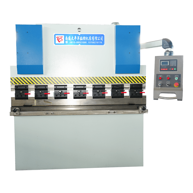
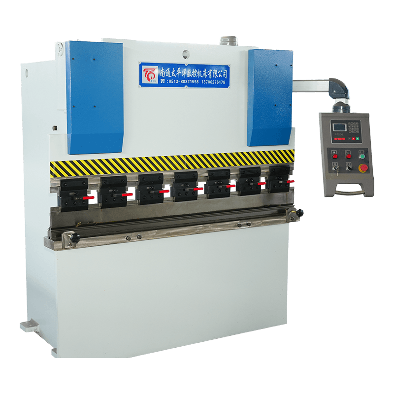 WC67Y-Series Hydraulic Sheet Metal Bending MachineThe WC67Y series hydraulic press brake is a cost-effective NC sheet metal bending machine widely used in metal fabrication workshops, HVAC production, and general manu...View Product →
An NC controller stores angle, backgauge and stroke data, while a torsion shaft keeps both cylinders parallel along the full length of the ram. The welded steel plate frame is the part that holds the geometry together over years of use, and builders commonly verify it with stress analysis before the first cut. This class is the usual compromise for job shops running small to medium batches with frequent job changes.
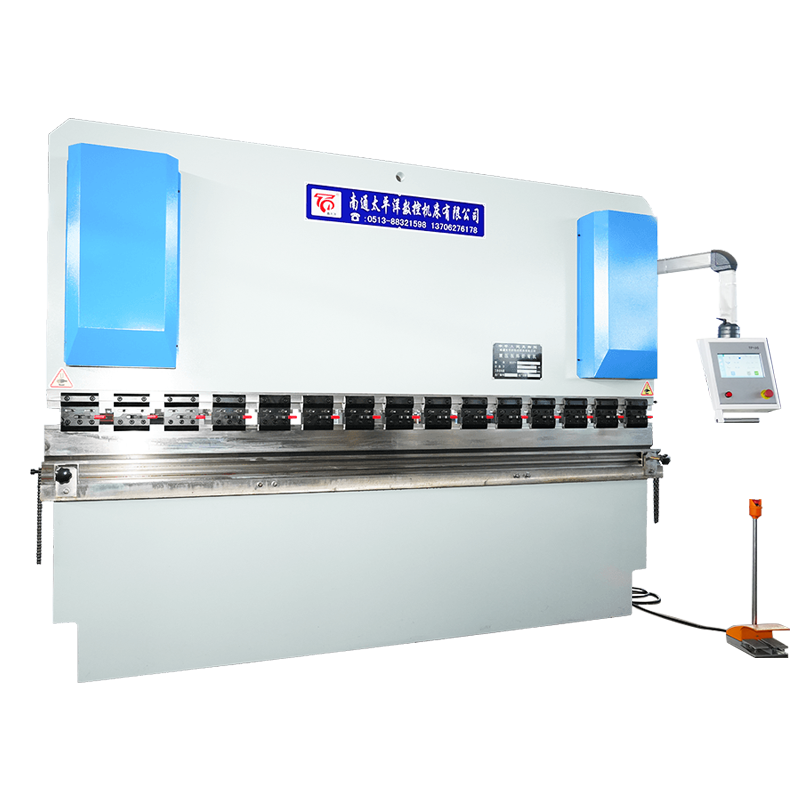 WC67K Series Torsion Axis Synchronous CNC Hydraulic Sheet Metal Bending MachineThe WC67K series torsion bar CNC hydraulic press brake is a mid-range, high-precision sheet metal bending machine, widely used in metal fabrication, electrical cabinet...View Product →
Two servo-controlled cylinders with independent position feedback, graphical control, bend-angle programming and often automatic crowning. Position repeatability is the reason to pay for it: on a 3,000 mm part with a ±0.5° tolerance, this class removes most of the trial bends and the scrap that follows a die change. It is the least forgiving choice if the shop only ever makes three of anything.
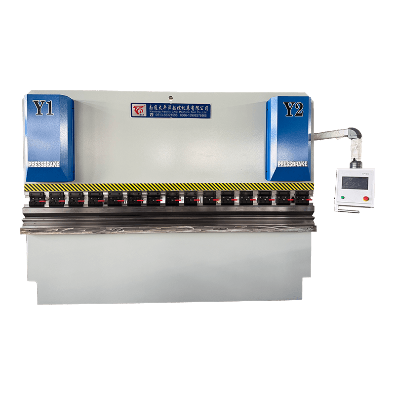
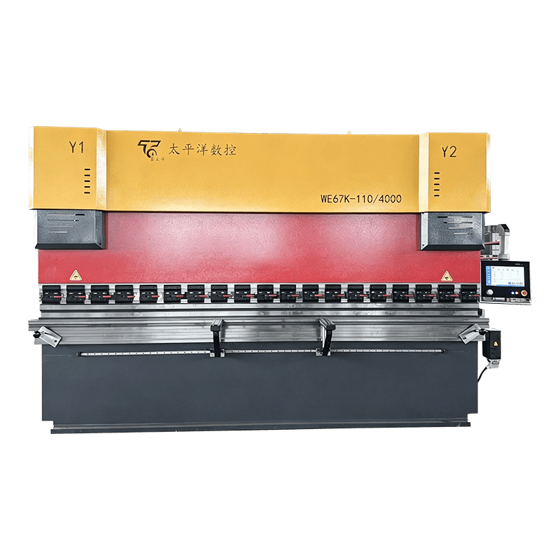 WE67K series electro-hydraulic servo CNC hydraulic sheet metal bending machineThe WE67K series electro-hydraulic servo CNC hydraulic press brake is a high-end precision bending solution developed by Nantong Pacific CNC Machine Tool Co., Ltd. It ...View Product →
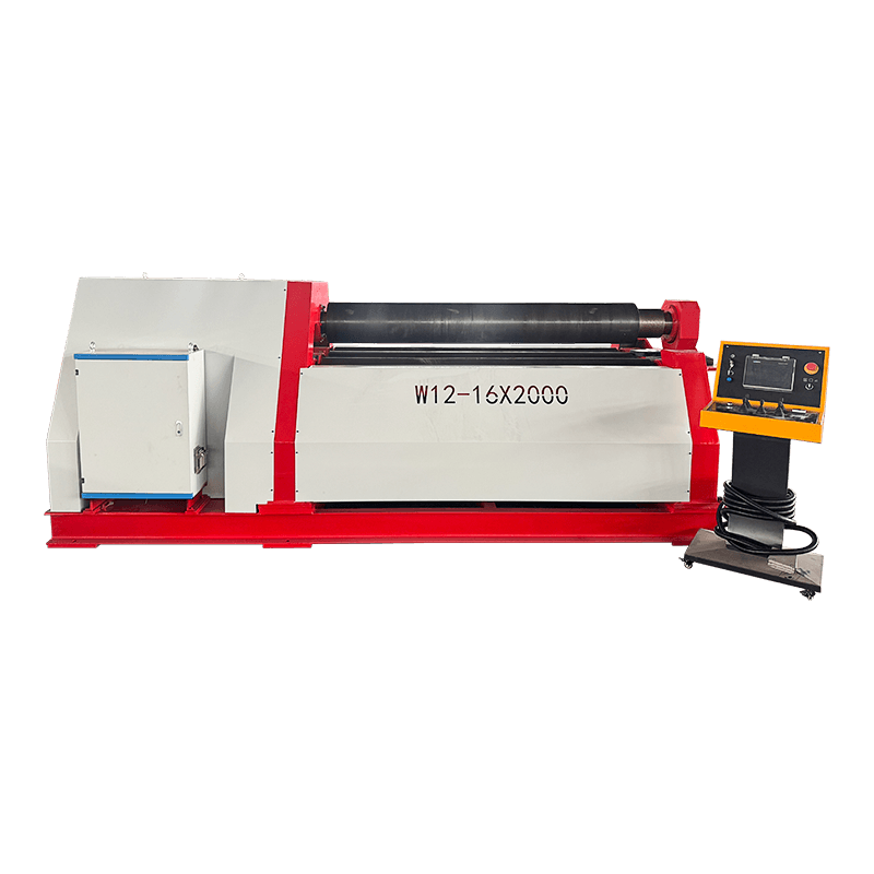
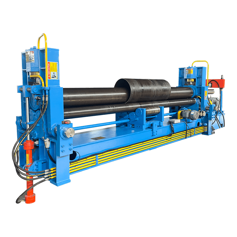
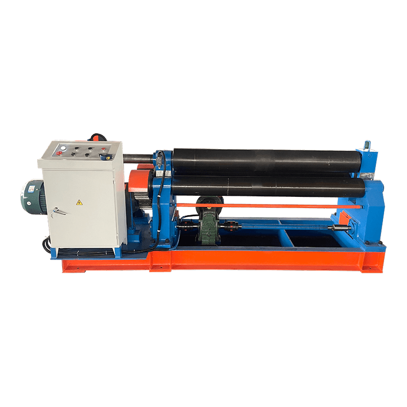
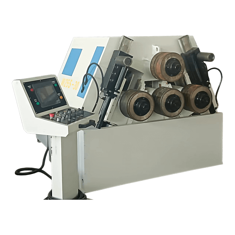
“Plate bending machine” is used loosely for two different processes. If the drawing shows straight flanges meeting at a defined angle, you need a press brake. If it shows a smooth radius — a cylinder shell, a tank body, a rolled cone — the correct machine is a plate rolling machine with three or four rolls, and a press brake cannot produce that shape at all. Many fabricators end up owning both, because a rolling machine cannot make a sharp 90° flange either. The rolling range with different roll configurations is described here: plate rolling machines.
An acceptance test costs half a day and prevents months of argument. Run these checks with your own material and your own part drawing, not with the sample the supplier brings.
| Check | How to test | Why it matters |
|---|---|---|
| Angle along the full length | Bend a full-length sample; measure both ends and the centre | Reveals deflection and whether crowning is working |
| Repeatability | Twenty strokes without adjustment; track angle drift | Shows what the ram position control is really worth |
| Backgauge accuracy | Program three positions, measure flange lengths with calipers | Flange dimensions depend on it entirely |
| Frame and ram deflection | Dial indicator on the ram under rated load | Permanent deflection cannot be adjusted out |
| Safety devices | Test light curtain coverage and hold-to-run function | Operator protection and compliance |
| Controller functions | Check tooling library, bend allowance calculation, program storage | These features decide setup time every day |
| Documentation and spares | Manual, wiring diagram, seal kits, tooling availability | Determines how long a breakdown lasts |
Most angle problems are born in the small area where punch, plate and die meet. The schematic below shows the working zone of a press brake in isometric view, so the tooling geometry and the force path through the frame are easier to picture.
Figure 3: isometric schematic of the bending zone — punch, plate, V-die and the bed that carries the load.
Two maintenance habits protect this zone: keep the die shoulders and punch tip free of scale and burrs, and check the hydraulic oil temperature and filtration on schedule. Both are cheap tasks that show up immediately in angle consistency.
Use bending force (kN) ≈ 650 × S² × L ÷ V for mild steel, where S is thickness in mm, L is bend length in metres and V is the die opening in mm. With V = 8 × S, one metre of 6 mm plate needs about 490 kN, roughly 50 tonnes. Stainless steel needs around 1.5 times more, aluminium about half.
A conventional hydraulic press brake sets the angle with mechanical stops, so every new job starts with trial bends. A CNC plate bending machine stores angle, backgauge and material data, so repeat jobs begin from a known program and the first part is usually acceptable.
Yes, with caveats. Type 304 stainless needs roughly 1.5 times the force of mild steel and springs back further, so both tonnage and tooling must be checked. The V-die opening and the punch tip hardness are usually the limiting factors, not the machine frame.
There is no fixed limit; it depends on bend length and available tonnage. The practical ceiling is where required force exceeds machine capacity or where the inside radius produced by the die grows larger than the drawing allows. Always compare force per metre, never total tonnage alone.
No. A press brake makes straight bends with defined angles; a plate rolling machine forms continuous curves such as cylinders and cones. Most metal fabrication shops that make both tanks and frames need the two machine types side by side, not one instead of the other.
In typical shop practice, setup drops from roughly 20–40 minutes on a conventional hydraulic machine to 5–15 minutes on a servo CNC model, mainly because angle, stroke and backgauge data are recalled rather than re-found. The saving repeats only where the work itself repeats.
Related Products

Contact us
Factory Address
Xichang industrial Park, Chengdong Town, HaianCity, Nantong City, Jiangsu Province, China
Phone
+86-13906278466
products
QR CODE

 English
 русский
 عربى
عربى