Aug 26, 2026
Specifying "smooth surface finish" without a measurable Ra value is one of the easiest ways to turn a routine fabrication job into a rework. A 200-piece stainless steel cabinet order was rejected last month for exactly that reason. Every bend angle measured within 0.5 degrees, every hole position was correct, and every panel matched its flatness callout. The problem was the surface: die marks on the bend radii, a scratch where the back gauge clamp dragged, and a faint roller imprint on one face. The drawing said "smooth surface finish," which meant something different to the shop floor than to the inspector. This article explains what a smooth surface finish really means, how it is measured, where forming equipment affects it, and how to specify it without paying for precision you do not need.
Content
Surface finish is not a single number. In engineering terms, surface texture has three components:
Figure 1. The three components of surface texture shown in an isometric view.
The most quoted parameter is Ra, the arithmetic average deviation of the profile from its mean line. A smooth surface finish in general machining usually falls between 0.4 and 1.6 µm Ra (16 to 63 µin; 1 µm equals 39.37 µin). Below 0.4 µm Ra, you need grinding, honing, or lapping; above 3.2 µm Ra, the surface feels visibly rough.
Rz, the average peak-to-valley height over the sampling lengths, is reported alongside Ra because it catches isolated peaks and valleys that Ra averages away. A surface can have a low Ra yet still contain a sharp notch that shortens fatigue life — that is why Rz matters for load-bearing parts.
Finish is not only about how a part looks; it changes how the part behaves.
To put smooth surface finish in context, the table below shows order-of-magnitude Ra ranges for standard manufacturing processes. Actual results depend on material, tooling, coolant, and machine condition.
| Process | Ra (µm) | Ra (µin) | Relative cost |
|---|---|---|---|
| Lapping | 0.012–0.4 | 0.5–16 | High |
| Honing | 0.1–0.8 | 4–32 | High |
| Grinding | 0.1–1.6 | 4–63 | Medium–high |
| Finish milling | 0.4–3.2 | 16–126 | Medium |
| Finish turning | 0.4–3.2 | 16–126 | Medium |
| Drilling | 0.8–6.3 | 32–250 | Low |
| Sawing | 1.6–12.5 | 63–500 | Low |
The same comparison is easier to read on a logarithmic scale, because Ra spans more than three orders of magnitude:
Figure 2. Typical Ra ranges by process, shown on a logarithmic scale.
For coil-fed cold-rolled steel, stainless steel, or aluminium sheet, the face finish is set by the mill and typically lies in the 0.5–1.5 µm Ra range. Forming processes preserve that finish rather than improve it — a different challenge from machining.
The standard shop-floor instrument is the stylus profilometer. A diamond stylus with a tip radius of 2–10 µm travels across the surface at constant speed, and its vertical motion is converted into a profile from which Ra, Rz, and related parameters are calculated.
One detail is often overlooked: the cutoff length. Roughness is calculated after filtering out longer waviness, and the filter cutoff must match the feature spacing you care about. For general machining, 0.8 mm is the common default; for fine lapped surfaces, 0.25 mm; for rough welded or flame-cut surfaces, 2.5 mm. If the cutoff is wrong, the Ra value on the report does not describe what you think it does.
For quick checks on the shop floor, calibrated comparator specimens (0.8, 1.6, 3.2, 6.3 µm Ra) remain the most practical method — as long as operators use them against the correct cutoff and scale.
Press brakes, shears, and plate rolls do not improve surface finish; they can only preserve it — or damage it. In most fabrication shops, surface complaints trace back to one of these three machines.
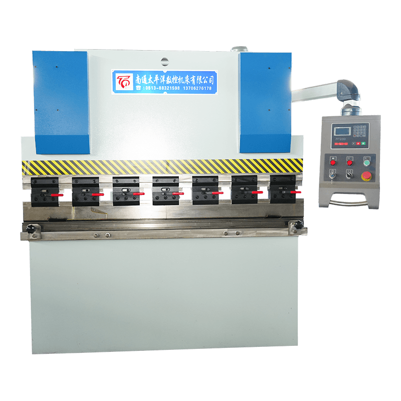
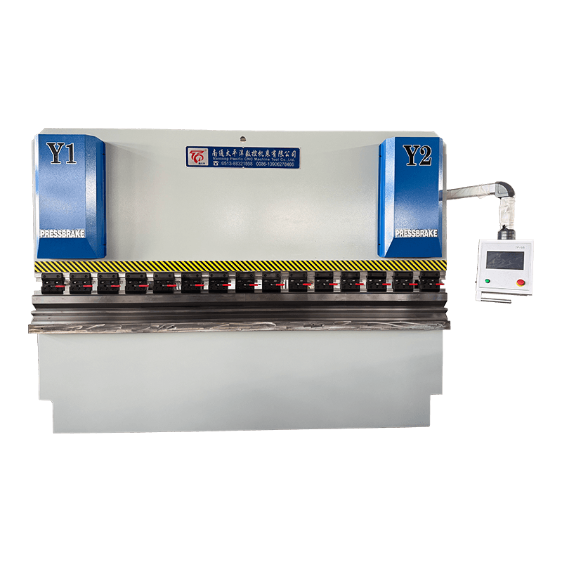
On a press brake, the visible face of the sheet is pressed between punch and die. Tooling scratches, galling from stainless steel, and die marks appear exactly where the customer looks. An electrohydraulic servo CNC sheet metal bending machine controls ram speed and position with more consistency than manual hydraulic valves, which reduces workpiece slide and tool-pressure peaks during the bend. Slower, more controlled clamping also lets operators use protective film or polyurethane tooling without tearing it, keeping the finished face clean. If the tooling is worn or the machine lacks repeatability, the same defects appear on every part. For a closer look at bend-line defects, see our guide on why metal cracks during bending.
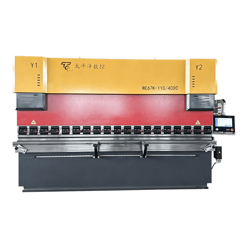 Electro-Hydraulic Servo CNC Hydraulic Sheet Metal Bending Machine ManufacturersNantong Pacific CNC Machine Tool Co., Ltd is China custom we67k series electro-hydraulic servo CNC hydraulic sheet metal bending machine ...View Product →
Shearing leaves a characteristic edge: roll-over on top, a burnished zone in the middle, and a burr at the bottom. Blade clearance is the main variable. Too much clearance creates a larger burr and a torn-looking edge; too little clearance wears the blade quickly and crushes the edge. A CNC hydraulic guillotine shearing machine with hydraulic hold-downs and adjustable blade gap produces a cleaner, smaller burr — which means less deburring before the part reaches the press brake.
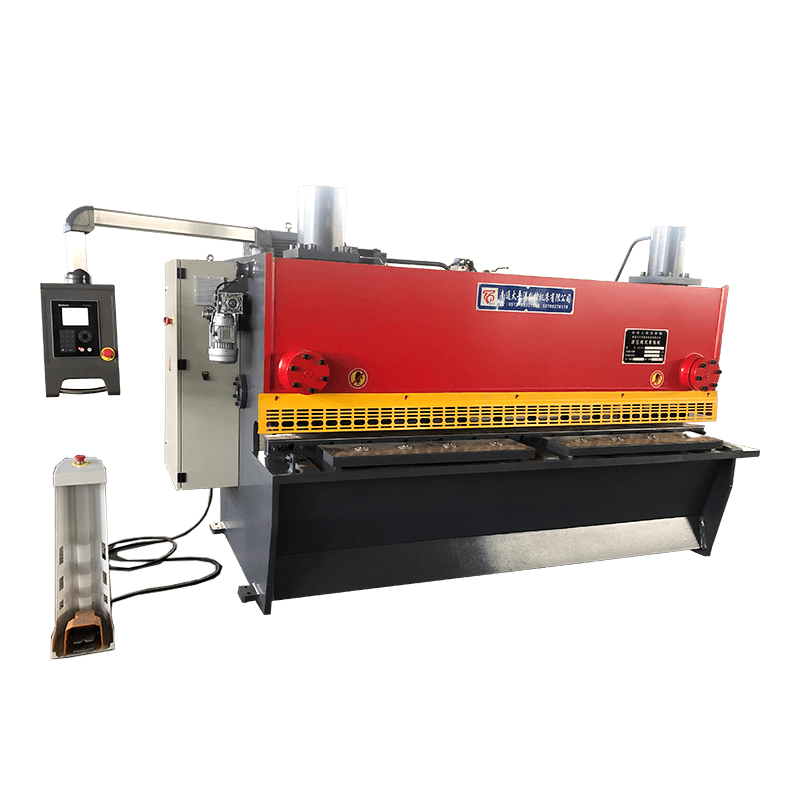 Hydraulic Guillotine Shearing Cutting Machine Suppliers, CompanyNantong Pacific CNC Machine Tool Co., Ltd is China custom hydraulic guillotine shearing cutting machine suppliers and hydraulic guillotin...View Product →
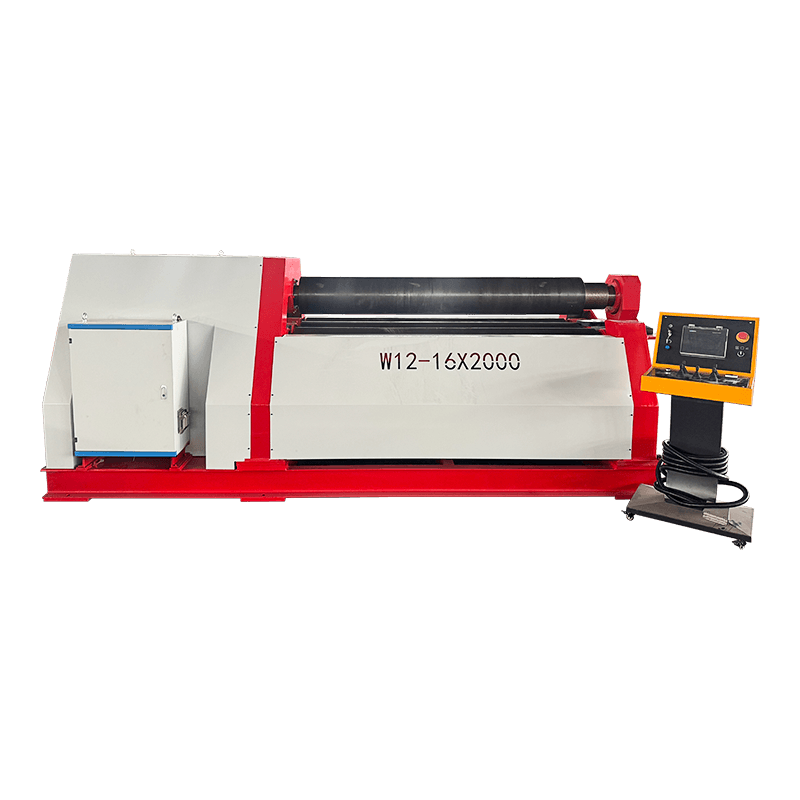
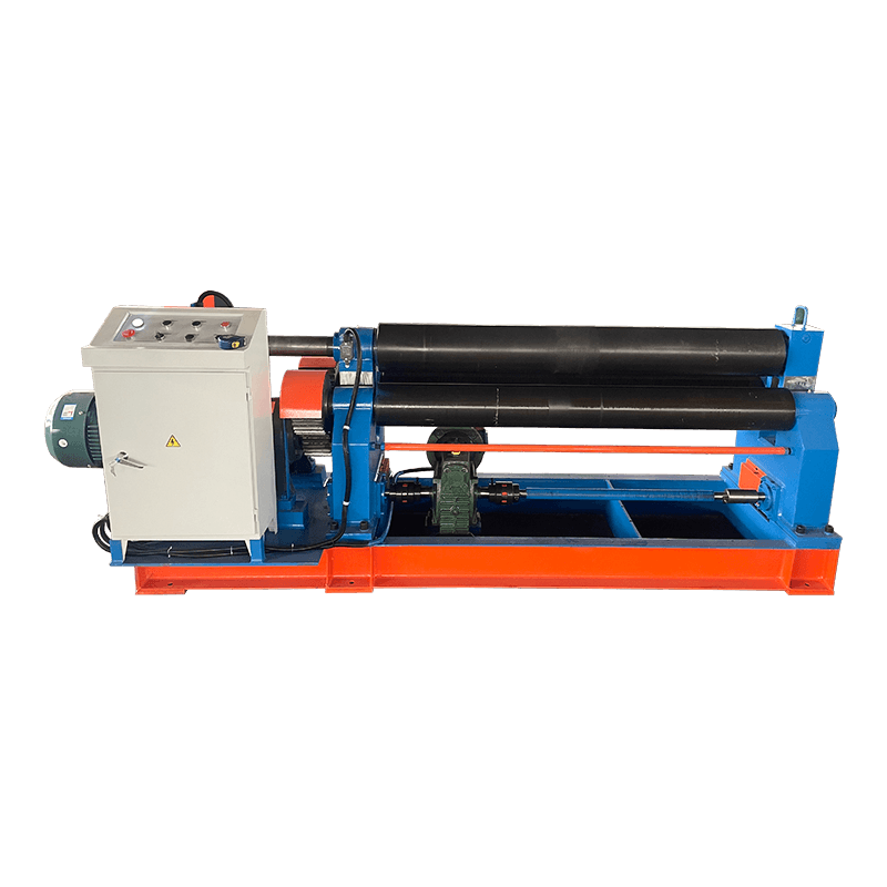
Rolling machines transfer the roll surface directly onto the plate. Any chip, pit, or weld spatter on the roll face imprints into every workpiece, and uneven hydraulic pressure makes the plate skid, producing scuffs during pre-bending. A three-roller universal hydraulic rolling machine with balanced pressure keeps the plate moving evenly and minimizes pinch marks at the plate ends.
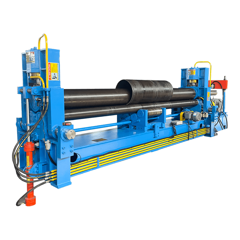 3-Roller Universal Hydraulic Rolling Machine Suppliers, CompanyNantong Pacific CNC Machine Tool Co., Ltd is China custom W11s series 3-roller universal hydraulic rolling machine suppliers and company,...View Product →
Choosing and maintaining the right equipment as a whole — the full range of sheet metal forming equipment for bending, shearing, and rolling — is the surest way to keep "smooth surface finish" from becoming a reject. Machine condition matters as much as machine type: ground tooling surfaces, clean rolls, and correctly adjusted blade clearance are what actually touch your part.
The most expensive four words on a drawing are "smooth surface finish," because they mean different things to the designer, the machinist, and the inspector. Every improvement in Ra carries a price. Going from 3.2 to 1.6 µm Ra may require an extra finishing pass; going from 1.6 to 0.4 µm Ra often means grinding or honing, plus added setup, inspection, and cycle time. The relationship is non-linear:
Figure 3. Illustrative relationship between surface roughness and machining cost, based on common industry experience.
A smooth surface finish usually means a machined surface in the Ra 0.4–1.6 µm (16–63 µin) range: smooth to the touch, no visible defects, but with normal process lay. On sheet metal, the mill finish is already smooth; the forming process must simply preserve it.
Ra, or average roughness, is the arithmetic mean deviation of the measured profile from its centre line. It is the most common surface finish value worldwide because it is simple to measure and compare. Use µm on metric drawings and µin on North American drawings; 1 µm equals 39.37 µin.
Use Ra for routine quality control and process monitoring. Use Rz when a surface must seal, resist fatigue, or avoid sharp notches, because Rz captures the height of the deepest valleys and highest peaks that Ra averages out.
Usually excessive blade clearance or blunt blades. Correct clearance for the material thickness, sharp blades, and a rigid machine frame produce a smaller burr and a cleaner edge. CNC guillotine shears with adjustable blade gap address this directly.
Yes. Clean tooling, protective film or polyurethane tooling, and controlled ram speed are the basics. Electrohydraulic servo CNC machines add consistent, vibration-free ram motion, so the sheet does not slide across the tooling and leave transfer marks.
As a rule of thumb, moving from 3.2 to 0.8 µm Ra can raise the cost of that surface by 50–150%, depending on part size and material. That is why over-specifying "smooth finish" on every face is one of the most common avoidable budget mistakes.
Related Products

Contact us
Factory Address
Xichang industrial Park, Chengdong Town, HaianCity, Nantong City, Jiangsu Province, China
Phone
+86-13906278466
products
QR CODE

 English
 русский
 عربى
عربى